Capacitor And Resistor In Series Voltage

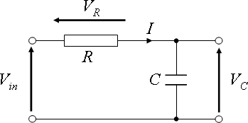
From the previous section we have seen that the capacitative reactance xc is shifted by 900 from the perturbing voltage signal and therefore is expressed in complex form as. In a series rc circuit connected to an ac voltage source the total voltage should be equal to the sum of voltages on the resistor and capacitor.

How Can The Voltage Across Capacitor Formula Be Calculated

How Can The Voltage Across Capacitor Formula Be Calculated

Parallel Resistor Capacitor Circuits Reactance And

Parallel Resistor Capacitor Circuits Reactance And

Complex Plane Diagram For Parallel Connection Of

Complex Plane Diagram For Parallel Connection Of

Impedance calculation the resistor will offer 5 w of resistance to ac current regardless of frequency while the capacitor will offer 265258 w of reactance to ac current at 60 hz.


Complex Plane Diagram For Parallel Connection Of

Capacitor and resistor in series voltage. Voltage lags current by 00 to 900. Voltage across each component in rlc series circuit. The voltage across the resistor will be same as the source voltage till the capacitor get charged assume the capacitor is uncharged previouslywhen the capacitor get charged the transient current will be zero so no voltage across the resistorthe decaying of the voltage will happen exponentially.

The simplest rc circuit is a capacitor and a resistor in parallel. Both are energy storage components but they differ in the way they store energy. Mutual repulsion of like charges on each plate drives the current.

The total impedance resistance of this circuit is the contribution from both the capacitor and resistor. In a series rc circuit connected to an ac voltage source the currents in the resistor and capacitor are equal and in phase. The voltage across the capacitor which is time dependent can be found by using kirchhoffs current law.

When a circuit consists of only a charged capacitor and a resistor the capacitor will discharge its stored energy through the resistor. Capacitor and resistor are the two most common basic components used in electronic circuits with each can be described in terms of the relationship between the current flow and the voltage across the component. Using calculus the voltage on a capacitor being discharged through a resistor is found to be a closing the switch discharges the capacitor through the resistor.

The voltage drop in resistor will be in phase with current in case of the capacitor the current will leads voltage drop and for the inductor the current of the inductor will be lag from voltage drop in the inductor.

Dc Circuits Containing Resistors And Capacitors College

Dc Circuits Containing Resistors And Capacitors College

Comlab Computerised Laboratory In Science Technology

Comlab Computerised Laboratory In Science Technology

Parallel Resistor And Capacitor In Non Inverting Voltage

Parallel Resistor And Capacitor In Non Inverting Voltage

Dc Circuits Containing Resistors And Capacitors Physics

Dc Circuits Containing Resistors And Capacitors Physics

Analyze A Series Rc Circuit Using A Differential Equation

Analyze A Series Rc Circuit Using A Differential Equation

Capacitive Voltage Divider As An Ac Voltage Divider

Capacitive Voltage Divider As An Ac Voltage Divider

Find Voltage Of Inductor In Lc Series Circuit With Resistor

Find Voltage Of Inductor In Lc Series Circuit With Resistor

Difference Between Capacitor And Resistor Difference Between

Difference Between Capacitor And Resistor Difference Between

A 200 Omega Resistor Is Connected In Series With A 5 Mu F Capacitor The Voltage Across The Resistor Is V R 1 20 V Cos 2500 Rad S 1 T A Derive An Expression For The Circuit Current
A 200 Omega Resistor Is Connected In Series With A 5 Mu F Capacitor The Voltage Across The Resistor Is V R 1 20 V Cos 2500 Rad S 1 T A Derive An Expression For The Circuit Current

Learn Electronics Capacitors Wikibooks Open Books For An

Learn Electronics Capacitors Wikibooks Open Books For An

You Connect A Battery Resistor And Capacitor As In Figure

You Connect A Battery Resistor And Capacitor As In Figure

Final Charge On Capacitor For An Rc Circuit Physics Forums

Final Charge On Capacitor For An Rc Circuit Physics Forums

Comments

Popular posts from this blog

Capacitors In Dc Circuits

Capacitive Voltage Divider Capacitor In Dc Circuit Lc Circuit Capacitor In Parallel When Capacitors Discharge Which Type Of Current Flows Finding Voltages Across Capacitors Under Dc Conditions Capacitors In Dc Circuits Physicslab Lc Circuit Ac In Rc Circuits Circuit Fundamentals Capacitors In Dc Circuits Electronics Fundamentals Ppt Video Online Download How Capacitor Works With Dc How To Select Dc Link Capacitor Application Notes By Electrocube Series And Parallel Capacitor Circuits Dc Fault Current Limiting Effect Of Mmc Submodule Capacitors What Is A Coupl...

2005 Toyota Highlander Blower Motor Resistor Location

Replace blower motor resistor 2000 toyota camry. This is how i replaced the hvac blower motor resistor in a 2005 tacoma. How To Replace A Blower Resistor Blower Motor Resistor Toyota Pick Up Troubleshooting Electric Cooling Fan Problems In Cars 1550 east camelback road phoenix 85014. 2005 toyota highlander blower motor resistor location . Jerry heasley recommended for you. Toyota highlander car heater blower motor resistor replacement costs between 111 and 279 on average. Issues in fan or blower. How to notice bad resistor in toyota blower or fan. Where is the location of the blower motor blower motor and resistor under the instrument panel on the passenger sidebehind glove boxdisarm airbag first. The best part is our toyota highlander blower motor resistor products start from as little as 1899. First let me say that this is the...

Capacitors In Parralel

This is shown below. By david santo pietro. Capacitors In Series And Series Capacitor Circuits Electrolytic Capacitors In Parallel Calculator Capacitive Reactance How To Solve Series And Parallel So connecting two identical capacitors in parallel essentially doubles the size of the plates which effectively doubles the capacitance. Capacitors in parralel . If youre seeing this message it means were having trouble loading external resources on our website. Capacitors in parallel capacitors are placed in parallel to provide higher levels of capacitance to provide an exact value that might not otherwise be available or to provide a distributed capacitance on a printed circuit board. V c1 v c2 v c3 v ab 12v. Here we have made use of the fact that the voltage is common to all three capacitors. When you connect capacitors in parallel youre essentiall...